File:Bridgnorth Signal Diagram.jpg

Summary
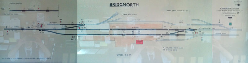
The signal diagram at Bridgnorth signal box, 17 October 2015. The black ovals are the track circuit indicators, which light red in the presence of a train (or if a track circuit fails). The pilot light in the top right corner would indicate that the diagram is receiving power if no track circuits are lit - except that on this day, the pilot lamp had failed!
The small label placed over the diagram at the right hand edge of Platform 1 is a modification to the distance to signals 4/18 - the signal had been moved 5 yards further from the box a few weeks previously.
Licencing
I, the copyright holder of this work, hereby publish it under the following license:
This file is licensed under the Creative Commons Attribution 3.0 License.
File history
Click on a date/time to view the file as it appeared at that time.
| Date/Time | Thumbnail | Dimensions | User | Comment | |
|---|---|---|---|---|---|
| current | 10:45, 17 October 2015 | 2,000 × 513 (196 KB) | Danny252 (talk | contribs) | The signal diagram at Bridgnorth signal box, 17 October 2015. The black ovals are the track circuit indicators, which light red in the presence of a train (or if a track circuit fails). The pilot light in the top right corner would indicate that the di... |
- You cannot overwrite this file.
File usage
The following page links to this file: